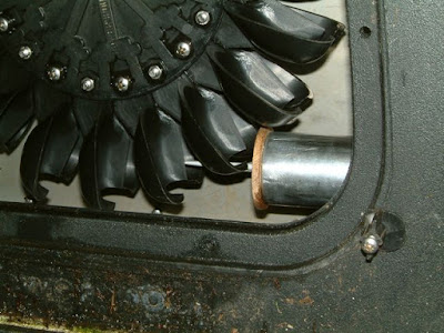
6.48 mm diameter nozzle delivering 0.91 l/s to the runner which is rotating at 1084 rpm and generating 225 watts into the grid at an overall efficiency of 47%.

Tuesday 30 June 2015

Another set of bearings on trial

Some things just don't work out as you hope: - today has seen the end of the ceramic bearing trial after just 28 days of continuous running.

Over the past week I had begun to notice a rumble coming from the Powerspout rear end and last night it became a more unhappy noise. As the turbine came to rest after shutting down, there was a clearly audible clicking as the shaft came to a standstill.  On inspection this morning, there was palpable free play in the shaft, - not much, but after so short a time, it was not worthwhile continuing the trial and risking a major bearing failure with damage to the Smart Drive rotor and core.

Michael Lawley commented when I told him about it that he had always had concerns about ceramic bearings, - "the only people who seem to use them are skate-boarders who would be lucky to do 100 hours".

So this morning was spent putting in a new bearing block, this time with SKF E2 Energy Efficient bearings.  I plan to run these with just their factory fill of grease, not adding any extra grease via the grease nipple.

Here are a few pics of doing the replacement to illustrate: 

  • how tightening the runner retaining bolt can be a one-man job 
  • a homemade tool for accurately aligning the runner to the jets:


Home-made tool to lock S-D rotor 


Tapping lugs into place in the holes in the rotor


Tightening to 38 ft lbs with the shaft locked


Piece of pipe which is a tight sliding fit in the nozzle holder,
with two wood inserts each end, bored dead centre
to take a 4 mm knitting needle


Device in place in bottom nozzle holder after removing nozzle


Close up of needle point on splitter ridge with just the
right number of packing washers behind the runner
to have the jet divided equally in two by the
splitter ridge. 


Saturday 13 June 2015

Shaft frictional losses

After 10 days, the ceramic bearings I reported in my last post are doing OK and it has been possible to revise upward the measurement of power gained by them from 9 to 10 watts, ie 0.24 kWh per day. 

The whole question of how much power is lost in the rotating parts of my turbine has been something I've been trying to understand better, and in this post I want to relate what I have found.

Before installing the ceramic bearings, I set about measuring the starting torque necessary to overcome friction in order for the bearings to start rotating.  I did it by hanging a syringe filled with water on the splitter ridge of a pelton cup, increasing the amount of water until it was just sufficient to start the runner rotating.  I then accurately weighed the filled syringe.

Having done this for the bearing block set up with ceramic bearings, I repeated it for three other types of bearing as follows:

  • a block with standard SKF bearings fully greased which had not yet been installed
  • a block the same as above which had done 7 months service
  • a block with SKF E2 Energy Efficient bearings having only the grease put into them at manufacture but no grease in the block, and not yet run
...and finally 
  • a block with E2 bearings as above plus with the shaft seal fitted (the seal which prevents water tracking along the shaft toward the outer bearing)
Here are pictures of the last two of these measurements, ie E2 bearings, with and without the shaft seal:

E2 bearings, no shaft seal:
20 ml syringe + 12 mls water,
total weight 28 grams
E2 bearings plus shaft seal:
60 ml syringe + 40 mls water,
total weight 78 grams


From the above, it can be seen the shaft seal adds 50 grams weight to what is necessary to just start the runner rotating.  Converting this to a torque: 50 g acting at 135 mm from the shaft centre is 66 N*mm (Newton millimetres).

It is now possible to work out how much shaft power is taken up in overcoming this frictional resistance.  The formula is: 
P (watts) = pi x T (Nm) x rpm / 30 
and it works out at 6.9 W, or 0.165 kWh per day.

Now clearly the shaft seal is an absolutely "must have" item, - it cannot be dispensed with: the power loss associated with it is unavoidable.  But for bearings, there are options to choose from and as has already been demonstrated, significant gains in power generated can be had by using ceramic bearings.

In the table below are the calculated values of power lost to friction, and energy lost per 24 hours, for each of the bearing combos investigated above. In each case, the calculation followed the same methodology as for the shaft seal:


I would want to stress that all of this is theoretical engineering, and also that I'm not an engineer or a mathematician, so don't go placing too much reliance on the absolute value of each figure. For one thing, the figures are based on a static test whereas in reality the situation is a dynamic one: the torque necessary to start a bearing rotating immediately diminishes as it begins to rotate but gradually increases again as speed of rotation picks up. This will mean that the starting torque used in the above calculations will not be the same as the frictional torque at 1000 rpm, - the operating speed of my turbine.

 But nevertheless, the figures are relevant for their comparative value if not for their absolute accuracy. Particular points of interest include:

  • how much friction there is after 7 months of running with a bearing block with standard SKF bearings.  I had thought they would free up with use but the opposite seems to be the case.
  • SKF E2 bearings appear to hold out the prospect of performing almost as well as ceramics, at least if the bearing housing is not greased and they are run as "greased for life" with just their factory grease.  Since they are considerably cheaper than full ceramic bearings, this might be relevant, but they would still have the drawback of being susceptible to corrosion from the ingress of water in a way that ceramics are not.

As ever, maybe the future operation of my turbine can be used to provide more clarity about these matters.  It'll be especially interesting to see how well these ceramic bearings last in the longer term.

Thursday 4 June 2015

On trial - ceramic bearings.

This week I have started a long term investigation for EcoInnovation into the use of ceramic bearings in a Powerspout.

These are ceramic versions of the standard issue 6205 and 6005 SKF deep groove ball bearings, but both the balls and the races are made of silicon nitride, Si3N4 (sometimes zirconium oxide, ZrO2) instead of steel.

According to Wikipedia: "since silicon nitride ball bearings are harder than metal, this reduces contact with the bearing track. This results in 80% less friction, 3 to 10 times longer lifetime, 80% higher speed, 60% less weight, the ability to operate with lubrication starvation, higher corrosion resistance and higher operation temperature, as compared to traditional metal bearings".


The desirable attributes out of this list which apply particularly to their use in a Powerspout are their resistance to corrosion, their reduced friction and their ability to operate with 'lubrication starvation'.

Their lubrication amounts only to a small amount of thin oil applied at the time of installation and being free therefore of the grease which surrounds the shaft when metal bearings are used, we had the expectation, having previously demonstrated that grease causes drag on the shaft, of seeing a significant improvement in power output.  

And indeed that is exactly what we saw.  The new bearing block was installed following a protracted run at constant flow with standard bearings, during which power output was measured to be 403 watts.  As I write, a 48 hour spell of running under identical conditions with the new bearings is just being completed, and the power level is now 412 watts.  So a gain of 9 watts.

OK, 9 watts isn't a huge amount but the thing to remember is that the power lost to frictional losses through shaft bearings and seals will be a fixed loss whatever level of power is being generated.  At the power level I am getting at the moment which is 412 watts, a 9 watt gain represents an improvement of just 2.2% over 403 watts.  But when flow diminishes and power yield falls to, say 175 watts, gaining 9 watts will be an improvement of 5%.

With the other improvements mentioned in earlier posts, all designed to boost output at low flow / low power times of year:

  • operating on one jet rather that two
  • changing to a reduced core stator
  • operating with a de-finned rotor
... there is the hope of greatly improving system efficiency in these drier months.

Already, the plot of flow vs efficiency suggests this might be so: the latest data points, which are indicated on the plot below, both lie well above the 'best fit line' for the other data points, all of which did not incorporate these improvements. 


If the left hand side of the above plot can just be flattened out a bit, which is to say if efficiency at low flow can be kept above the rather dismal levels it falls to below 1.5 litre per second, then this would amount to a real benefit.

Let's hope !