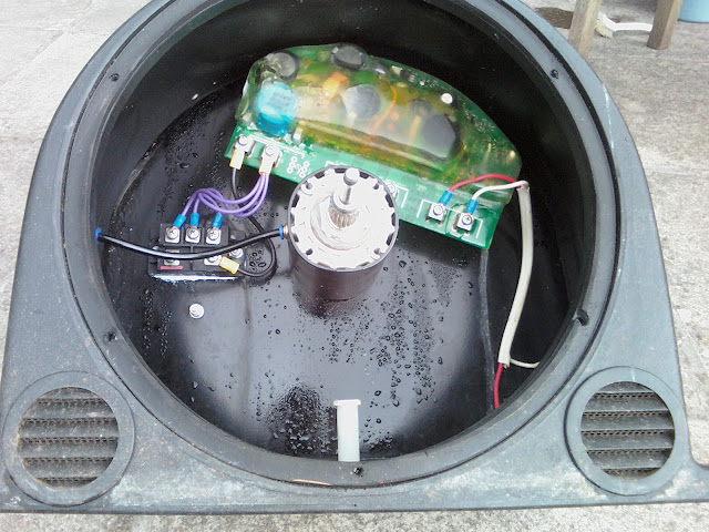
At the time, it was pretty disappointing, but I'm happy to give credit where it's due: - Ecoinnovation were superb in their support both of me and their product, and readily honoured their warranty. They came up with a specially re-worked board encased in epoxy which has stood the test of time and is still the one in the turbine now.
Reading this week of a fellow Powerspout GE400 owner whose board failed in January this year, and for whom Ecoinnovation also readily provided a replacement under warranty despite it being 3 years after his original purchase, I thought the matter worth writing about. The issue is likely to be something which, sooner or later, will affect anyone with a GE400 turbine.
To recap on what this circuit board does and why it is needed:
- it changes the ac output of the SmartDrive alternator to a dc output for the inverter
- it ensures the resultant dc output does not exceed 400 volts by two means, the second being failsafe for the first:
- diverting power to a water cooled heating element when voltage reaches 380 v
- shorting the output if voltage reaches 400v
- capping of the dc voltage output is necessary because an inverter will be irrepairably damaged by voltages greater than its rated input voltage (400 v for the obsolete Sunny Boy 1200 but now 500 or 600 v for current Enasolar inverters)
- voltage WILL rise to very high levels when the turbine is unloaded and the electrical output is in open circuit because:
- the pelton will accelerate to runaway speed (which is ± 1.8 x optimum speed)
- the voltage output of a pma is speed dependent so as the pelton over-speeds, so over-voltage will result
- it is a characteristic of pma's that they exhibit poor voltage regulation and voltage rises when there is no circuit connected to the output.
- such open circuit / unloaded operation of the turbine / generator is an inevitable occurrence which will happen every time the set is run up (because of the time it takes for the inverter to wake up and check the grid for compatibility before connecting) and every time the inverter disconnects from the grid for whatever reason.
So the need for voltage capping is unavoidable and the V-Clamp board pictured above and devised by Andrew Smithies was a really neat, failsafe and compact solution which tidily sat within the Powerspout casing.
Unfortunately, that location within the casing was also its Achilles heel. In spite of the slight warmth created by the alternator, in spite of the ventilation provided by the fins on the rotor, and in spite of giving the board a generous conformal coating of silicone, water penetration to the board led to failures:
| Tell-tale ooze of melted silicone with underlying blackening gives away where the problem was on the reverse side of this board |
| With the silicone removed, there is clear evidence of arcing across the pcb surface between the terminals of this power MOSFET on this board |
| With circuit board removed leaving behind the white heat transfer paste showing where it was attached, the evidence for water trickling down from the board is clear. |
With several dampness related failures of the board, Ecoinnovation was forced to withdraw from its range the GE400 and other turbines using a similar board. But with developments in inverter technology which saw inverters able to accept up to 600 v, together with using Smart Drive cores configured to deliver a lower operational voltage and thus lower open circuit voltage, things came together to keep the grid connected Powerspout as a viable option.
The need to cap voltage was not completely eliminated however and instead of the neat arrangement of having the board within the casing, this is now provided by a range of products which need to be housed separately. One of these products comes from a UK company called 2V Microsystems Ltd under their trade name Klampit and another is a product from Chinese company Ginlong.
Sooner rather than later, obtaining a replacement original V-Clamp board is going to be impossible. When that time comes, moving over to a Klampit will probably be my best option but that will involve, for me, having to figure out where to house the extra components. Being out in the open, I don't have the wall of a turbine house to mount these extras.
In the mean time, I am hoping that my epoxy encased 'special' will go on working for a while yet. And in case it doesn't, I have carefully kept my two failed boards as they are repairable if not too badly damaged. The secret is in knowing how to remove the generous coating of silicone: put the board in the freezer at -23 ℃ for a while and then it mostly breaks away leaving the components on the board pristine. But be warned, lots of patience and several returns to the freezer will be needed.
 |
| My 'special' epoxied board, repair of which will never be possible. Note also condensation on bulkhead. |