In previous blog posts on battery storage, I waded through the deliberations that burdened me as I struggled to reach a decision about proceeding with it; in this post, I just want to show what actually came of it all.
In a future post, I’ll look at the system's pros and cons, but I'll write that when more time has passed with it being operational. At present, it has only been operational for 6 weeks. In that time our energy consumption from the national grid has been less than 5 kWh (before it was 200 kWh for the same 6 week period in previous years), - so early impressions are favourable.
Location for 'battery bunker' BEFORE construction
Battery bunker AFTER completion
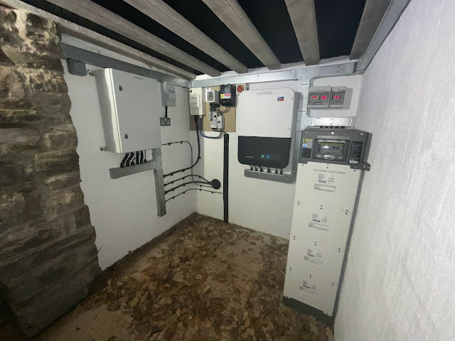
Inside the bunker
Meters for ac frequency and volts, and battery dc volts; the switch is the 'black start switch' for manual operation of battery back-up
BYD HVS battery tower, 4 battery modules totalling 10.24 kWh, with Battery management Unit on top
SMA Sunny Boy Storage 3.7-10 inverter with ac ON/OFF switch
Connection compartment at bottom of SMA inverter; additional devices on the right are a DIN rail mounted, 5 way, Ethernet switch and its 12vdc power supply
Cable entries to underneath of Enwitec Battery Back up box; the Enwitec box accomplishes all the switching arrangements for transfer from grid supply to battery supply when there is a grid outage, and back again to grid when the grid is restored; this it does either automatically or manually; manual control is by means of the "black start switch".
The inside of the Enwitec box; The key component monitoring power flow at the grid connection point is the SMA Home Manager 2; it is the device to which the green Cat 6 (shielded) ethernet cable is plugged into. The contactor Q1 on the left side is the device which isolates the property from the grid when battery backup is in operation. Relay Q3 is the device which ensures grounding of the neutral conductor when in battery backup mode. F1 and F2 are mccb's protecting the power supply to the Enwitec box, one for grid supply and one for battery backup supply; F201:1 and F201:2 are respectively an mcb and a rcd on the ac line connecting to the SMA SBS inverter.
The incoming National grid supply, and its meter, were moved into the bunker from their previous place in an outside receptacle on the wall of the house; this was to make more simple the cabling arrangements for battery back up; the earthing arrangement when on grid supply is TT, and on battery back-up operation it changes to TNCS.

In the house, two new consumer units were installed, one for house loads and one for in-coming power from the two renewables available:- these are the Powerspout and 3.2 kWp of solar; the total generation from these two renewable sources is measured by an SMA Energy meter; this is the device with a red ethernet cable connected to it; the data from the Energy meter is made available by Ethernet cable connection, via a LAN network, to the SMA Home manager (in the Enwitec box housed in the bunker); also, the data from all devices in the system is made available, via a www connected router, to SMA's web interface; this they call Sunny Portal; next year 2024, for systems which have a Home Manager, SMA will be replacing the classic version of Sunny Portal, with their new web interface called Sunny Portal powered by ennexOS; when that comes, the User interface will have, so they say, a new fresher look.
The user interface provides all the expected features of instantaneous and historical energy flows that one expects from such technology; the parameters and configuration of the SMA SBS inverter can also be accessed directly via the LAN network, and this is essential in setting up the system and for investigating faults when they arise; following SMA's advice, which they strongly encourage, I went for cabled communication throughout, rather than using WiFi.
This is our meter measuring in-coming energy from the national grid; the pencilled readings top and bottom were the readings on the day when the battery storage first started operation, and that was 41 days ago; you can see that in those 41 days only 0.6 kWh of low rate energy has been used, and 3.1 kWh of normal rate; in that time we have cooked, heated our domestic hot water, charged our Nissan Leaf umpteen times, and met all the 'base load' requirements of a normal modern house; as I mentioned at the start, normally this would have taken around 200 kWh, - so the battery has, thus far, been 'transformative' !
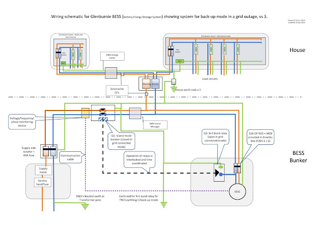
For the really technically minded enthusiast, here are the schematics for the scheme as it was finally constructed: