In Wales, September and October is when water supply is at its lowest. It's the time when the water available to my Powerspout is diminishing steadily.
Such is the series of nozzles I use that as water supply decreases, a step change happens in the amount of water delivered to the turbine every time I put in a nozzle with a smaller orifice.
But the rate at which the autumn decrease in flow occurs is steady and leisurely, and sometimes the change between two nozzles in my series is too great, - the system gets to miss out on some of the flow of water even though it is there for the taking. It is for this reason I have found myself needing to cut a nozzle which is an 'in-between' size, in-between the size of two existing nozzles.
The challenge facing me was twofold: first to decide what orifice diameter would deliver the in-between size I was aiming for, and second how to cut that size precisely.
To resolve the first, I needed to understand the relationship between orifice size and flow. Clearly, head pressure determines how much water passes through an orifice, but when considering a single installation, head pressure will remain the same for all sizes of orifice and so doesn't enter into the relationship.**
This leaves orifice size and flow being the only two variables, and knowing these for all the nozzles I use, I plotted one against the other to get the graph below. The mathematical formula defining the relationship of flow (y axis) to orifice diameter (x axis) is conveniently given by the Excel graphing program:
The two red arrows mark the positions of the two nozzles between which there was too big a step, - I needed to cut a nozzle which was as near as possible midway between them, and that would be a nozzle having an orifice of 5.7 mm, giving a flow of 0.73 litres / sec.
So far so good !
But cutting the nozzle to the required size was not easy. I do this job on a wood lathe (see here) and if you take off too much the orifice is too big. For this reason my first effort failed and the second almost ended the same way. In the end, I had to be content with a diameter of 5.8 mm which, according to the graph, will deliver 0.75 l/s. It's the point on the graph marked with a blue arrow.
You might think that such precision in trying to cut a nozzle to an accuracy of 1/10 of a millimetre is over the top, - and you're probably right ! But this 'in between' nozzle will probably be the right one to use for the next 2-3 weeks until the steadily diminishing flow eventually makes it too big to use. My reckoning is that the extra kWh's of generation it will make possible in that 2-3 weeks, as compared with the smaller nozzle I would have had to use, will make the exercise worthwhile.
Time will tell.
Noted added later: to my surprise, the rains came early; instead of flow diminishing, it started picking up; so the in-between nozzle only found itself in use for 10 days.
** Head pressure can drop with higher flows if the penstock has too small a bore but having a generously sized penstock and with the meagre flows my turbine takes, head pressure can be taken as constant.
Note that the plot will only be true for sites having the same head as mine, i.e. 53 m, and will not be correct for a site with a different head.
Summer dryness is making itself felt here and today I've made the change I make every year at about this time, - changing the 42 pole stator to the reduced version which has only 18 poles*. The effects of doing this were two:
- the rpm of the turbine increased from 793 to 885; this makes the efficiency at which the pelton converts hydraulic power to shaft power rather better (my optimum pelton speed is about 1000 rpm)
- the rotor, which had to be packed off maximally to keep the rpm up to 793 with the 42 pole stator, could now not be packed off at all; this makes magnetic flux linkage between stator windings and rotating magnets better and so improves the efficiency of the alternator.
The benefit of these two efficiency improvements are apparent in the record of the turbine's output to the grid. The output can be seen to have been lifted from 206 to 227 W.
OK, so it's not a huge increase in output, - just half a kWh per day. But I needed to do the change so that as flows decrease further, I have the Smart drive set up for the coming weeks as I go down through my nozzle sizes. As you can see from the output record, it only took 30 mins to do.
*see here and here to read about the reduced core stator
EcoInnovation, the company in New Zealand making Powerspout turbines, has developed a new jet nozzle. It's longer and more tapered than the original and the change in design slightly changes the way the nozzle performs. There is a theoretical flow an ideal nozzle will deliver which is dependant on the orifice size and the pressure head. However in the real world the actual flow is less than the ideal by what is called the Discharge Coefficient (CD), and it was the CD for the new nozzle which needed to be measured. This is how it was done.
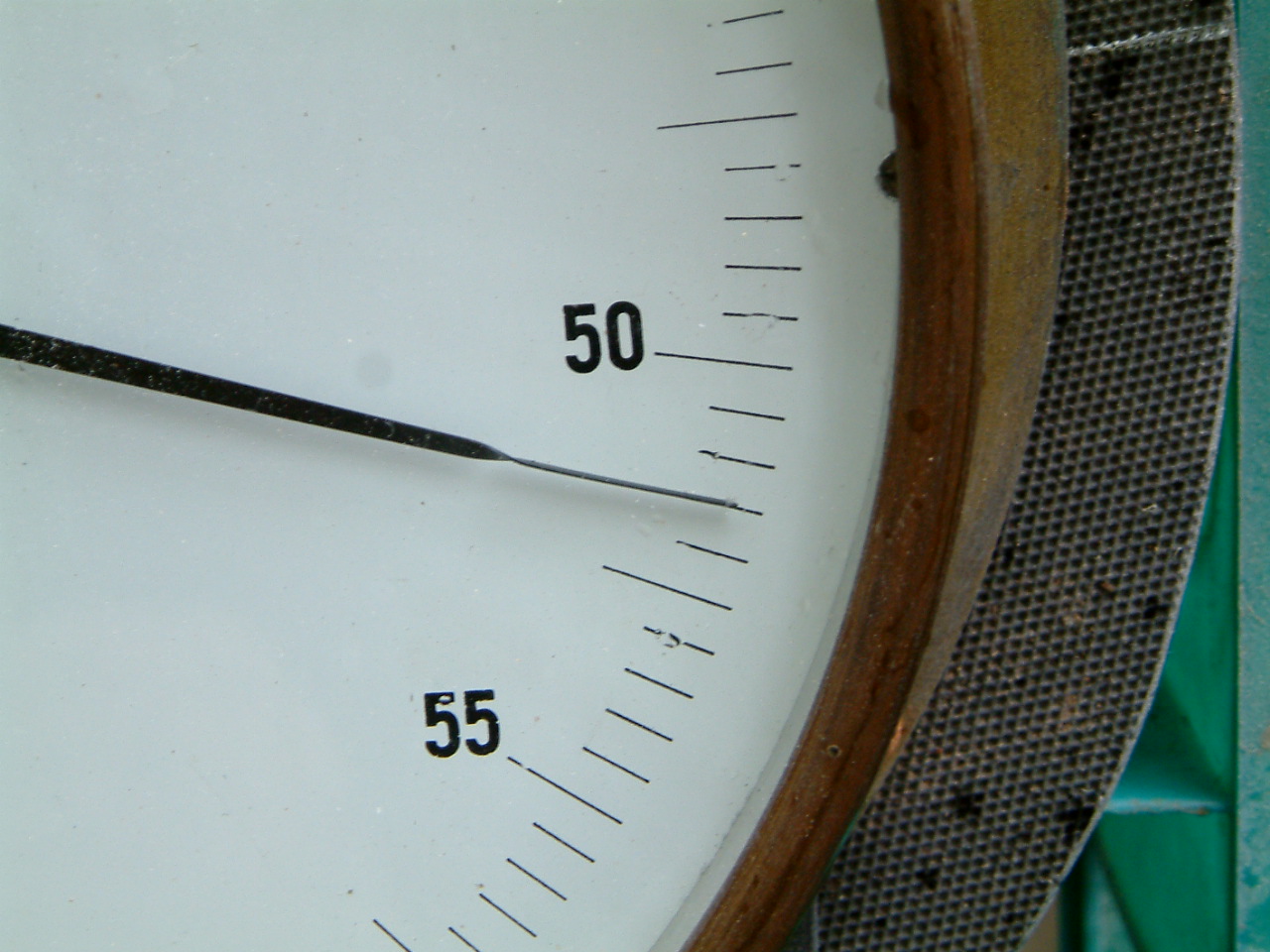
1. The formula* for determining CD requires net head to be known, - net head being the water pressure at the entry to the nozzle when it is operating. The very large pressure gauge in the picture, calibrated in metres head of water, provided the means for measuring it. Plumbing it to the manifold required the temporary removal of the upper pelton jet.


2. The formula also requires the flow through the nozzle to be known. This was determined by measuring with a stop watch the time it took for a defined volume of water to pass through the orifice. This defined volume was 429.5 litres. It was known to be this because a drop in water level in the header tank of 104 mm could be calculated to be equal to this volume. The height drop of 104 mm was determined by two knitting needles set exactly with their points that distance apart. The stop watch was started when the surface tension 'grab' to the upper needle was broken and was stopped when broken again at the bottom needle. The inflow of water to the header tank was diverted while each measurement was made. The measurement time varied between 131s for the nozzle with the largest orifice and 20m 11s for the smallest.
3. For 13 nozzles with different sized orifices, paired sets of net head and flow measurements were obtained. The Discharge Coefficient for each nozzle was then calculated and the results, with the flow for each nozzle, plotted in MS Excel:
4. As can be seen, the Discharge Coefficient is not the same for all sizes of nozzle. For the smallest size, nozzle I, where the flow is least, the CD is close to unity** indicating that actual flow is the same as would be expected from an ideal nozzle. But as orifice size increases, the CD falls.
5. The new type of nozzle performs better than the old. Old nozzles had a mean CD of 0.85 whereas the new 0.90.
6.The value of Discharge Coefficient for a nozzle depends on the pressure difference between the pressure of water entering the nozzle and the pressure once it has left through the orifice. So although on my site (which has a pressure head of between 51.5 and 53.6 m depending on flow) the CD has been measured as indicated above, the same nozzle on another site with a different pressure head will have a different CD, though it won't be greatly different .
* Q = CD x Anoz x Sqrt (2g x Hnet) whence CD = Q / (Anoz x Sqrt (2g x Hnet))
** The result obtained was 1.01, i.e. better than unity, which is not possible and represents experimental error.