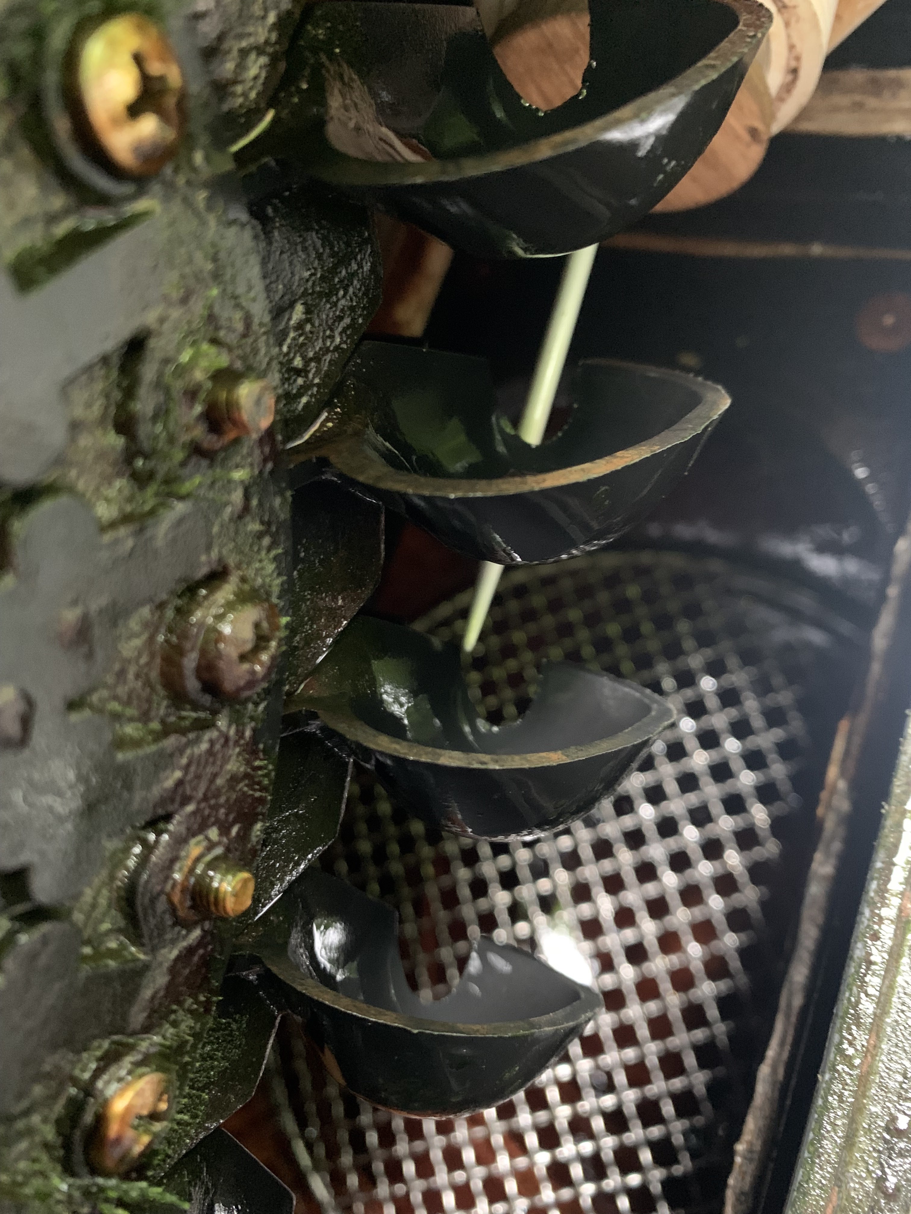
6.48 mm diameter nozzle delivering 0.91 l/s to the runner which is rotating at 1084 rpm and generating 225 watts into the grid at an overall efficiency of 47%.

Tuesday, 29 August 2023

53,760 hours.

 53,670 hours is the number of hours in just over 6 years, and this week I decided after this length of time it was time for the bearings to be changed; this blog illustrates what everything looked like when I took the bearing-housing apart having never disturbed it in all that time.

I installed the bearings on 5th July 2017 and they were SKF E2 Energy Efficient bearings; they have run continuously ever since bar one period of 48 hours in October 2018 when there was insufficient water; the only other times when the turbine shaft has not been turning is when a nozzle is changed, or the stator is changed, and such stoppages are typically for only a matter of minutes.

Of particular note is that the bearings have not been greased at all; neither was grease preloaded into the bearing housing when they were first installed; they have operated only on the grease put in by SKF at manufacture.

I made the decision to change them only because 6 years seemed a long enough interval; there were no warning signs of impending failure that prompted the change; literature from SKF suggests that the bearings can be expected to be serviceable for up to 9 years; after this length of time the grease will have come to the end of its ability to lubricate and 10% of a batch of apparently identical bearings will fail; this metric for predicting the likelihood of a bearing failing is called the T10 life expectancy; it is very much dependent on the conditions under which the bearing is operating, especially the load it is carrying, the temperature it is operating at, and most especially whether water and other contaminants can get to the rolling parts.

6 years is thus within the T10 life expectancy for the bearings - except the big unknown is the conditions under which they are actually operating.

So here is a pictorial account with captions of what the seals and bearings looked like: -

on my turbine, I have a specially made cover to help prevent water ingress; its purpose is to give a metallic face for the V-lip seal to rub on; it fits over the plastic 'Top-hat' and is held in place only by being a tight fit. 

a puller was needed to get it off.

another modification I have made on my turbine is this deflector to discourage water from entering the drainage hole of the 'Top-hat'

the first glimpse of the condition of the shaft indicated that little moisture was getting to it


for comparison, this is a picture from the previous bearing replacement in 2017, which was done after just 14,448 hours of operation and before steps were taken to prevent water ingress; it shows limescale encrusting the shaft, indicating that quite a bit of water was getting in.

detail of, and explanation of, the marks on the shaft; the brown colouring was of silt-like consistency and rubbed off very easily with wire wool; the surface of the shaft was not scored where it had been polished by the seal.

I was surprised by how much the stainless steel of the cap had been worn by the rubbing of the V-lip seal; it was almost as bad as the wear on the plastic of the Top-hat in the next picture, except that the plastic wore to be like this in a matter of months.


when I had removed the dust shields of the two bearings, the grease around the balls still looked pretty good


a close-up of the balls shows they were still well lubricated

SKF's E2 bearings have a very different looking ball cage; this is what the reverse side looks like.


the radial shaft seal on the inner end of the Top hat was a bit mucky; it has two lips and the second picture is a close up of the space between the two lips showing it to be full of the silt like material present on the shaft.

In summary, the bearings looked good enough to do another few years, but the seals were in need of being changed. The feel of the shaft rotating in the housing was of very free rotation as if the bearings were well 'run-in'. By comparison, when I had put in new bearings, of the same sort, the rotation felt rather stiff and not so free.

Unsurprising then that when I powered up the turbine with its new seals and bearings, power output was 16 watts down on what it had been, - that's a 4% loss of efficiency, - down from 44% to 40%, taking efficiency here to mean whole system efficiency, ie water-to-wire.

Ah well, - better a small drop in generation now than having the bearings fail later, - possibly in winter and having to do the job of changing them on a cold, wet day, as an urgent rather than an elective undertaking !

Monday, 19 June 2023

A lesson learned

Even after 10 years, I am still learning about my Powerspout; today the lesson has been how minutely critical the alignment of the jet to the pelton wheel needs to be for maximum power to be generated.

My lesson came about like this: the turbine had been running very sweetly on 1.23 l/s, generating 331 watts into the grid, at a water to wire efficiency of 51.2%, - when I took it upon myself to disturb this happy state of affairs by putting in a wire-mesh grill; the grill was to sit beneath the turbine and stop me dropping parts beyond reach of retrieval when I do a nozzle change.

To slip the grill into place required the plinth on which my turbine sits to be lifted a very small distance, - but to lift the plinth requires the pipe manifold to be separated from the Powerspout casing, and to do that, the jet-cum-nozzle assemblies have to be removed.

No problem I thought !

After re-assembly, I was perplexed to find that the previous output of 331 W was now only 250 W, and the overall efficiency had dropped to 41.2%.

Nor did the turbine look or sound right; the splash pattern was not what it had been and there was the sound of some water missing the pelton and hitting the opposite wall of the Powerspout casing.

What followed was much experimentation with packing washers behind the runner, measurements using my knitting needle alignment tool (see this blog) and checking and rechecking what else could have been inadvertently put out of alignment.

Eventually, it was a hammer and a piece of wood that solved the issue, - by judicious tapping of the jet-cum-nozzle assembly whilst the turbine was running.

The tapping restored the original happy state of affairs by moving the assembly tiny amounts within the bounds of the hole in the casing through which the assembly passes, with these barely perceptible movements being judged good or bad only from observation of the splash pattern and from the sound the turbine was making.

Creating a Powerspout installation is a labour of love; having created it, everyone wants 'their baby' to generate as much as their site conditions allow; as this lesson teaches, it's worth checking that your jet alignment really is optimal.

Here are some pics to put flesh on the day's adventure:

Wire mesh grill in place beneath where pelton runner normally is attached to the shaft.

Using knitting needle tool to optimise alignment of runner to centre of jet.


 "if all else fails, 'it it wi' 'ammer" !

Monday, 12 June 2023

Optimising my inverter turbine curve

 The inverter that connects my Powerspout to the grid does more than just convert DC power to AC; by the load it imposes on the alternator, it determines the speed at which the shaft turns, and the speed at which the shaft turns is critical if a pelton is going to extract the maximum power from the head and flow of water available.

I run my inverter in what is called 'turbine mode'**; run like this, the load the inverter imposes on the alternator is determined from a 'mathematical table' stored in memory in the inverter, that tells the inverter how much load to apply depending on what DC voltage it is receiving from the alternator.

The 'table' is really an equation relating DC input voltage to AC output watts, and whilst a new inverter is delivered with a table chosen by the manufacturer, the table can be changed by the user.

A user might want to change the table because the factory parameters may not suit the performance characteristics of his hydro site, in particular the inverter may not allow the pelton to rotate at its optimum speed; the table in the inverter will work with the factory settings but it will almost certainly not work to produce the very best efficiency.

In a small hydro installation where power outputs are so small, tweaking efficiency to the best possible is a good idea to get the installation to be as productive as possible, and it has been for this reason I've been playing around with optimising the table in my WindyBoy inverter.

Without going into more detail than is necessary to explain how a table relating DC voltage to AC watts is constructed, some familiarity with Microsoft Excel is required.

The relationship between these two parameters is described by a single equation relating x and y, where x is DC voltage and y is AC watts.

The factory default table uses the equation: y = 0.0001x^3 - 0.0306x^2 + 2.92x - 83.

When this is plotted on a graph with x values chosen to be in the range of the DC voltage produced by my Powerspout, it produces the green curve in the graph:


Last year, I spent time carefully investigating what voltage produced the most watts output, for each of the nozzle sizes I operate my Powerspout with over the course of the year.

As a result of that exercise, I came up with a revised table, giving a revised curve, which is shown by the orange line. You can see it is a flatter curve than the green one and that at low power outputs (100 to 150 Watts) when the DC voltage is around 170 volts, the line starts to curve upwards without ever reaching the x axis.  The effect this had in practice was that at this low level of power output the inverter failed to connect to the grid, - presumably because the look-up table confused the inverter regarding the load it should be applying.

Last year therefore, I could not continue to generate with my smallest nozzle (0.53 litres/s) using the inverter with this table in its memory and I had to swap to another inverter which still had the factory default table.

This year, with summer progressing toward the driest time of year in September / October, I wanted to find a curve which would be able to work at this low flow. Playing around in MS Excel has yielded the blue line in the graph which I hope will do the trick.

You can see it almost overlays the orange line for most of its course, and that is good because it means it will make the inverter operate at the optimal points determined by my investigations last year, and crucially it does not start to curve upwards when power outputs are low.

Time will tell if my playing around has worked. Already in the few weeks I have been using this revised curve, when flows are still around 1.5 litres/s, there is a marginal improvement in power output compared to the orange curve, lifting water to wire efficiency by just one half of a percent! (53.3 to 53.8 %).

Every efficiency gain counts !

Here's a picture of loading the revised formula to the inverter from a laptop, running SMA's WindyBoy set up programme, and using SMA's USB Service Interface cable:


** Most inverters used for Powerspouts are solar PV inverters which are programmed to operate in Maximum Power Point Tracking mode; MPPT works for a hydro; but in this mode the inverter is constantly seeking the maximum power point, which for a water turbine is not changing, and so the output is seen to be constantly fluctuating when it could be a nice straight line.