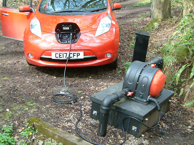
6.48 mm diameter nozzle delivering 0.91 l/s to the runner which is rotating at 1084 rpm and generating 225 watts into the grid at an overall efficiency of 47%.

Sunday, 31 December 2017

System efficiency at top-end flows

December has been a better month, - we've had 118 mm of rain, which is double what fell in November and three times what fell in October, - and it's now working its way through for me to see a pleasing uptick in generation.  Units of energy generated in December were 312 kWh (a figure which is poor for December) and the capacity factor for the month was 56%.  At the moment the turbine is putting out 892 W from a flow of 3.26 l/s and these are heights of power and flow which I have never before aspired to.

The explanation behind such an unprecedented level of generation is that I've been waiting for a time when there was copious flow so I could run some tests to check what the system efficiency is at the top end of the range of flows I see at my site. To do this I have had to run the installation a little beyond the limits imposed by the various authorities that licence small hydros: strictly the output should not exceed 750 W and the maximum flow 3 l/s.

Previously in this blog, I presented a plot like the one below to illustrate how operating with one jet in the bottom position was more efficient than operating with both jets:


With the data I had at that time, the plot seemed to show there was a clear advantage to using only one jet and in the bottom position - it gave an improvement in system efficiency of about 2 %, and this advantage seemed to apply throughout the flow range, - although it should be noted that data points for single jet operation are sparse for higher flows, there being only one.

Having copious water available at the moment, it has been possible to get data readings for the larger nozzles very easily, and this has meant I've been able to fill in the gaps in the earlier data series and better define what happens at the top end of the flow range.  The resulting plot, which is based on a completely new data set, now looks slightly different:


... it will be seen that when a very large single jet is employed, one that delivers 3.12 l/s, the efficiency starts to drop off and begins to fall below the trend line for two jet operation.

I'm not sure why this should be. There shouldn't be any question of water from this bigger nozzle missing the cups on the runner: the cups are 70 mm wide and the diameter of the jet 12.2 mm. Maybe it's just that there's a lot of splash from the force of this big jet and that impairs the efficiency.

Some of the reason for the fall-off in efficiency beyond a flow of 2.5 l/s in both single and two jet operation is that shaft speed begins to rise away from the optimum speed for the runner. I have found that with flows greater than 2.5 l/s I have needed to change from the standard Type 2 rotor to the more strongly magnetised Type 2+ rotor. This keeps the shaft speed down to nearer the optimum speed, which for my site is 1000 +/- 100 rpm.  At the moment, generating as I am 892 W from 3.26 l/s, the shaft speed is 1165 rpm.  Were I to push the experimenting and deliver even more water to the runner, the downward trajectory of the efficiency curves for both single and double jet operation would fall off steeply as shaft speed began to rise despite the 'braking effect' of the Type 2+ rotor.

As it happens, I don't want to do such an experiment: the inverter I have is a WindyBoy 1200w and for continuous operation (as is the case when the inverter is coupled to a Powerspout) the output rating of 1200 W has to be down-rated to 900W.  Not wanting to roast the inverter, I think I'll just stay at 892 W.

Saturday, 16 December 2017

Grid failure

This past week has seen snow falling where I live.  However well Western Power, the electricity distribution company for our area, has done its job of cutting back overhanging trees from the power lines, snow always brings problems.  In this past week we have had repeated power outages and I thought it worth writing a Diary entry on how a grid connected Powerspout pelton behaves in such circumstances.  

When the grid goes down, the turbine will continue to receive water and the energy of that water has to have somewhere to go,- where it goes depends on whether it is an older or newer type Powerspout and on what type of inverter is handling the interface between the turbine and the grid.

... the original "grid enabled" Powerspout, the GE 400, which is the one I have, manages the situation by diverting power which cannot pass to the grid whilst the grid is down by sending it to a small heater load which is splash cooled by the spray within the wet side of the turbine casing: 


 Diversion is controlled by an electronic control board, housed in the dry side of the casing, and this regulates the power fed to the heater element so that system voltage is kept at 380 volts DC.


The necessity of keeping voltage at this level is dictated by the inverter I have which is an early one marketed in 2011. It is unable to accept voltages higher than 400v DC.  The electronic control board locks system voltage at 380 v, just below the inverter's limit and thus keeps the inverter from being damaged by over-voltage.

... later, inverters came on the market capable of seeing an in-coming voltage considerably in excess of 400 v: - the 2 kW Enasolar inverter, for example, is quite happy with 600 v.  This development in inverter technology opened the door to managing grid outage situations in a completely different way, a way which was much simpler and did away with the need for a control board.  

Instead of diverting electrical power to a load, electrical power ceases to be created at all by keeping the system in open circuit: with no load connected what happens is that system voltage rises as the pelton runner goes to its run-away speed but, crucially, no current flows.  And so long as the system voltage rises to no more than 600 v the inverter remains safe.  What becomes important with this way of managing grid outages is that a stator must be selected which is wound in such a way that even at the highest run-away speed possible for the site (which is determined by the net head), the open circuit voltage will never exceed the inverter's limit.

You may well ask "but what happens to all the hydraulic energy in the system if none of it now finds an outlet by being turned into electrical energy?" The answer is that a lot of it never gets as far as being translated into shaft rotational energy. At the run-away speed of the pelton much of the water passes through the pelton runner, which is moving just about as fast as the water jet, without ever hitting the pelton cups.  The water ends up hitting the casing opposite the nozzle and its energy is dissipated as heat and sound. Some extra energy is also lost as heat in the bearings and shaft seal - a greater amount at the higher speed at which the shaft is revolving at run-away speed than is lost at normal operating rpm.

To illustrate some of this, here is a picture of a pelton at run-away speed showing how the water from both nozzles fails to be deflected in the normal way onto the front glazing because the velocities of both runner and jets are little different:


This pelton was coupled to an Enasolar 2 kw inverter which, at the time, was not connected to the grid; the run-away speed of the turbine which resulted was measured at 1440 rpm:


and because the stator of the SmartDrive had been carefully selected to be one which delivered just 0.266v /rpm in open circuit (it was a 100-14S-1P S stator), the open circuit voltage at runaway was measured at 383 v: well below the 600 v limit of the inverter.

So there have been two ways of managing a grid outage with a Powerspout pelton and both are good.  This past week with its numerous grid outages has reminded me just how "bomb proof" my system is: when the grid goes down, the turbine continues happily feeding power to its dump load and after the grid comes back on, seamlessly the turbine re-connects itself to the grid.  It's all clever stuff and it gives me great pleasure to see it in operation.

Sunday, 1 October 2017

End of year results.

Good data about small hydros is hard to come by.  By good I mean energy data which is trustworthy, granular enough to show daily output and historical enough to allow comparison of one year with another. Measures such as 'Capacity factor' and 'Availability factor' are also nice parameters to see reported.

But such data is scarce so it's always a high point for me to come to the end of my 'accounting year' and be able to present my figures.  

The 'accounting year' I use runs from October 1st to September 30th so today is the day I have been able to wrap up the figures for the past 12 months.  Presented graphically as a cumulative plot of kWh's generated the results look like this:


...and the same data presented as a daily plot showing generation on each day of the year, the results look like this:


 Both plots show data for this year (purple) and for the previous three years. 

Though the figures for hydro generation are interesting enough in themselves, many very small hydro installations will be coupled on the same premises with a small solar installation, and it's nice to be able to see how the one compliments the other.  Here then are the corresponding graphs for my 3.3 kWp PV which has been operational for only two years:


It doesn't need a magnifying glass to spot some of the comparisons to be made between the hydro and solar yields:

  • solar is hugely variable on a day-to-day basis but the cumulative plot in one year follows almost identically that of the previous year;  hydro by contrast has almost no day-to-day variation (a step change occurs only when a nozzle change is made) but the cumulative plot lines are widely divergent from one year to the next.
  • the yield from hydro does well from November to May, whilst solar does well from March to September; late October is the time when total 'domestic generation'(i.e. the daily sum of the two) is at its lowest.
  • on the evidence so far available, the total per year for my domestic generation will lie between 5800 and 7200 kWh.
This last bit of information, i.e. generation being between 5800 and 7200 kWh/year, has been a key driver in my exploring 'battery-on-the-wall-storage' at home.  Our domestic consumption of electricity is about 6000 kWh/year but because cooking (our heftiest use) always takes more power than is being generated, we end up having an annual take from the grid of about 1700 kWh.  I have been exploring whether it might be feasible to reduce this by storing domestic generation into a battery when there is a surplus, - a few hundred watts at any given moment but over several hours, - so that it can be used for cooking when the need is for 3-4 kW but for a short time only

And a 'battery-on-the-wall' offers two other possibilities: the possibility of purchasing and storing grid energy when the tariff is cheap then using it at a time when the grid tariff is high, and the possibility of having an 'uninterruptible power supply' for the whole property for times when grid outages occur.

So data collection has its uses. It can inform how best to move with the times as new developments like 'home battery storage' come on the market. The man is coming to see me about battery storage next month.  I'll report back.

Monday, 7 August 2017

Peltons past and present.

I've recently acquired a new pelton wheel, - only it isn't new, - it was made in 1905 by an engineer who, at that time of his life, lived and worked from a small town about 40 miles from here. His name was Percy Pitman and here is an article he wrote for the October edition of 'The Engineer' in 1905. I guess it's probably him in the picture:


It's worth remembering that 1905 was only 25 years after Lester Pelton, living in Ohio, USA, filed his patent for an impulse turbine having cups with a splitter ridge, so the cups effectively became two cups side by side. Prior to this, cups were more like a single bucket and the water entering them had to bounce back rather than be streamed outwards to each side.  Pelton's design made the wheel significantly more efficient.

The wheel which has come to me was for sale in a farm auction.  Where I live, when a farmer retires, it is usual for him to have a sale of his old equipment, - everything from tractors to scrap wood and steel. The farmer who was retiring had bought this pelton at a similar farm auction some years before, but had never done anything with it. By the look of it, the lack of wear on the buckets indicated it had NEVER done any real work:


Back home, shot-blasted, painted and mounted on a frame which I picked up from another farm auction, the wheel is beginning to look presentable.  I'm intending to put it close to my Powerspout so people passing can understand what a pelton wheel is.  I'm amazed at how many people have never heard of the word !  Here's how it looks now with a Powerspout pelton next to it to give an idea of size:


Life sometimes throws up odd coincidences !  A few weeks after getting my pelton, a friend drew my attention to an advertisement for the sale of ANOTHER pelton wheel, almost certainly by Percy Pitman because of having identical construction and being located in the vicinity of Bosbury where he lived, but this time a more complete example than mine:


To have TWO historic pelton wheels become available within weeks of each other is a truly unusual event.  And to learn that one hundred years ago, in this part of Wales, there was a man making his name by the manufacture of such wheels gives a nice historical dimension to my Powerspout operating today.  

There's one curiosity that remains with me though: - my pelton is NOT well made; the cups are steel castings bolted to a circular steel plate, but they have not been attached around the circumference in a way that makes them equi-distant from each other, - at one side they are crowded together and at the opposite side spaced more apart.  The effect is that the wheel is badly un-balanced and a rather crude effort was made to balance it by bolting on a strip of steel. I have removed it because it was rusting badly and the rust was eating into the circular steel plate, but where it was attached can just be seen by the presence of two bolt holes at the wheel's 12 o'clock position.

Perhaps Percy Pitman was not the meticulous engineer he advertised himself to be ! Certainly he quickly left behind the manufacture of 'industrial' pelton wheels to pursue the manufacture of "hydraulic equipment for educational establishments".  But judging by the progressively more prosperous houses he occupied in London he must have died a well-to-do gentleman and a far cry from his humble beginnings in Bosbury, Herefordshire where he started out.

Postscript added Nov 2019:
More about Percy Pitman can be found here.

How the finished wheel looks:


Thursday, 6 July 2017

14,448 hours

A couple of days ago I noticed the Powerspout wasn't sounding right. This is the sound of it coming to a standstill:


The bearings have not been changed since 10th November 2015 and that's 14,448 hours ago. The turbine has run continuously for all of that time bar stoppages for nozzle changes and one de-silting of the header tank.  Clearly the time to change them had arrived and in this post I want to tell how things looked after such a protracted period of operation.

The bearings at each end of the bearing housing looked completely unremarkable; a small amount of the SKF Lesa 2 grease I have been using was evident at both ends, more or less equally distributed between the two ends, and was only a little grey in colour at the pelton end:


My greasing regime has been 4 pumps from a small grease gun once a month (0.8 grams / 1.4 ml per month).

From the encrusting on the length of shaft that sits in the 'top hat water flinger', it was evident that quite a bit of water penetrates into the 'top hat'. The picture below of the wet side of the SOG seal shows a tide mark to half way up it suggesting that water enters more quickly than it can quickly exit from the drain hole: 


Crucially however, there was no evidence whatsoever of water getting past the lip of the SOG seal, and had it done so, the notch cut in the bearing housing to allow it to drain downwards was fully patent and not blocked with grease which had passed through the pelton-end bearing.

The bulkhead showed where water had been striking it and it was pleasing to see this was a mirror image of the splash pattern seen on the front glazing, - indicating that nozzle alignment directing the jet onto the splitter ridges of the cups was pretty good:


The old bearings were taken out and thoroughly examined by dismantling them.  At first there seemed to be little damage to explain the rumble that had indicated the end of their working life, - but on examination with an eye glass there was spalling in the groove of the outer race and this pit was evident at one point in the groove of the inner race:


Spalling* in the groove of the outer race: 


These bearings were SKF units (made in China) as supplied by EcoInnovation. What I have installed in their place are SKF E2 energy efficient bearings which I do not intend to grease at all, - relying on their factory fill of grease to last for their entire working life.


EcoInnovation encourage Powerspout owners to change the bearings every year and this is undoubtedly the right advice: 14,448 hours is 4 months short of 2 years so it is better to stick to an easily remembered 12 month regime.  The exercise described here of pushing the boundary to see how long I could get bearings to last was just an experiment - and it has been an instructive one too.

Here is how new bearings SHOULD sound as the turbine comes to a standstill:


*Spalling is when tiny flakes of material are broken off from the wearing surfaces of a bearing and become deposited in the grooves where the balls run making them no longer smooth.

Tuesday, 13 June 2017

Work productivity - human and hydro.

Lately, the human kind of productivity has been encouraging but the hydro kind less so.  

To take the hydro kind first, - the line of the graph of cumulative kWh's generated for the current year continues to fall away from the trajectories taken in previous years:


...we have had rain, but it has been meagre and not done anything to increase energy output.  I doubt the year total will see 3000 kWh, - which would mean a 25% reduction on last year's total.

This disappointing output is not a result of any interruption in turbine operation, - it has run continuously with no interruption caused by the near miss of the tree falling next to it, - work on the clearing of which is the reason for the encouraging productivity of the human  sort:


The clearing away of the root plate of the tree is still a work in progress.  It's all being done with hand tools so it takes a while.

As I work on it, trying to remove each and every stone amongst the roots that will mean another sharpening of the chain saw's teeth, I keep telling myself "Rome wasn't built in a day", which alternates with "There are worse things to be doing in retirement"!

My thanks to my mate Paul, emptying his boot of saw dust in the picture. Without our arguments about how best to do the job, life would be less fun.

Saturday, 3 June 2017

A different sort of Powerspout

Up 'til now, these diary entries have all been about my Powerspout installation. Last month I visited an elegant scheme that is quite different, - instead of being low flow with several meters of head like mine, this one was high flow with just 2.7m of head.

I'll let the pictures tell the story:


The installation comprises two Powerspout Low Head Pro turbines generating into a single 2 kW Enasolar inverter which is grid connected.  With both turbines running, the power into the grid is just over 1 kW; the operating voltage is 204v dc. Using the Powerspout calculator to 'back' calculate how much water is actually passing through the two turbines, I get it to be 82 l/s.

A lot of water is needed for these low head sites, but as can be seen, at the time of year I visited, at this site there was more than enough, - with much overspilling via the rectangular holes cut into the tank.

With regard to how noisy they were, there was so much sound from water splashing from the over flows that I couldn't hear the turbines themselves at all.

...a nice set up!  My thanks to the owner, - with whose permission these pictures are posted.

Friday, 28 April 2017

...a close call !

Just after 8 am this morning, my Powerspout had a narrow escape. No damage was done and the output afterwards was 15 watts greater, - presumable down to the single jet that was in use being nudged into better alignment.


...and it's noticeably quieter encased in mud !

Thursday, 13 April 2017

Earth fault ? - no problem !

Addenda to original post: see end for latest situation.

Lately, the inverter connecting my Powerspout to the grid has been signalling an error message.  I've got to the bottom of it now and cured the issue but the journey has been an educational one which I thought might be helpful for others to know about.  The inverter is an SMA Windyboy, which is the same as the SunnyBoy, and what I describe only applies, I think, to these two SMA inverters.


The error message was "Earth Fault". Since the supply from my turbine is not intentionally grounded this meant a possible fault in the turbine, or possibly on the cable coming from the turbine to the inverter; fortunately the inverter continued to operate so I felt in no hurry to get to the root of the problem.
In this situation, SMA's trouble-shooting guide instructs you to exclude a genuine earth fault by inspection and testing. If this first-off approach doesn't reveal what's wrong, the next step is to test the 2 varistors housed within the inverter because, the guide says, a failed varistor can cause the Earth Fault warning to be displayed.

In an SMA inverter, the varistors look like this:


Each has 3 wire tails and when the insulating shroud is removed, each is revealed to be a composite of two components: a varistor connected in series with a thermal fuse.
The trouble-shooting guide says to test for continuity between B and C, ...if there is no continuity the assembly needs to be replaced; if continuity exists, ...look for a fault elsewhere in the inverter.
It was only sometime later, after I had removed the insulating shroud and seen there were two components beneath it, that I realised testing in this way only tests for continuity across the thermal fuse; it cannot test the functionality of the varistor itself, which is the blue disc-shaped component.

When I did the continuity test, both the varistor-cum-fuses showed continuity, and so I concluded, as the SMA literature had led me to believe, that they were OK.  But a week later, having exhausted all other possible causes of the fault condition, I replaced both with new ones and, hey presto, no longer was Earth Fault displayed: I had got to the bottom of it 😊. (** - but see post scripts below)

So what's the 'science' behind all this ?  The purpose of a varistor is to eliminate voltage surges which might damage the equipment the varistor is protecting; they are 'sacrificial' devices, meaning they can be destroyed by the excess energy they absorb, and they are also 'wear' components, meaning they gradually lose their function from the cumulative effect of absorbing energy from lesser voltage surges which are not great enough to destroy them.

In extreme situations, varistors can catch fire, either because of the magnitude of the energy passing through them or because of the duration the energy flow exists for.  In this situation they pose a fire risk which might destroy the very device they are meant to be protecting and to mitigate this, a thermal fuse is sometimes included in series with a varistor, - a fuse which will 'blow' and terminate the supply through the varistor if its temperature exceeds a set point.  This is the arrangement of the two components found in what SMA call 'their varistors'. 

SMA state that 'their varistors' are specially manufactured and are not commercially available, - except, of course, from SMA. The cost (in 2017) is €15 plus shipping and VAT (total €29.75), for a pack of two (part code SB-TV3, with insertion tool).

The two components that make up 'their varistor' can however be found on the open market, and with a soldering iron to connect them in series, they can be made up more cheaply. The varistor is an Epcos S20K320 (Vrms 320v, VDC 420v, Imax 8000A, Wmax184 joules Pmax 1 W) and costs 0.55p from Farnell (order code 100-4305).
The thermal fuse is more difficult to find but I managed to track down 6 on eBay: it is a Tamura E3F 250v, 3A~, 115℃ and each one set me back €2.20, inclusive of p&p. But it can also be purchased direct from China for less than this.

Why should the varistors have failed in my inverter to cause the Earth Fault warning? I figure that with 12,492 hours of continuous operation, at ~300v DC, the natural 'wearing' process going on in a varistor is accelerated and probably accounts for their failure. After all, an inverter handling power from a water turbine operating all the time sees a lot more use than one connected to a wind turbine or PV array. 

12,492 hours is about 17 months and so I'm thinking this is the interval at which I should expect to see the Earth Fault warning recurring, - and therefore that I should have enough stock of the varistors and thermal fuses to meet that sort of replacement frequency.

It was nice to have gained a little more understanding of how the technology was designed to work.

** note added 3rd September 2017: the fix turned out to be not long lasting. Within 2 months, the inverter was displaying Earth Fault again, initially intermittently and then permanently.  Replacing the varistors yet again, with new SMA ones, failed to get the fault light to extinguish***.  I conclude that either there is truly an earth fault somewhere or the sensing circuitry within the inverter has gone wrong.  I think the latter more likely.  It being an issue which does not affect performance, I plan to do no more about it.

***yet another note added 12th March 2018, - following my further replacement of the varistors, which failed to extinguish the earth fault warning, I did nothing.  After a while, I'm not sure how long, perhaps 2 weeks, the earth fault warning DID disappear, - and it has remained off ever since up to the time of writing this note. Perhaps new varistors just take time to 'bed in'.

****an even more recent note added 4 Aug 2018, - the warning light remained off as related above, until 3rd July 2018; from then it has been on constantly; so today I first replaced the varistors again: no change, - and then removed them completely: still no change.  It would seem therefore that the varistors are not the cause, as was surmised above, but if the warning light extinguishes in the next few days, that hypothesis will not be right.  I'll post another update if that is the case.

*****this saga runs on and on ! - and since I see from Blogger stats that quite a few people visit this posting, I have written this latest update.- this one is dated 22 Oct 2018. 

  • As recounted above, on 4th Aug I removed the varistors completely and the earth fault persisted.  Being somewhat fearful of operating without the varistors, I re-installed them sometime late in August.  Earth fault was still displaying. 
  • I then changed out the entire inverter for a brand new one (also a Windy Boy 1200) and the earth fault STILL displayed.  So at this point I had to conclude there truly WAS an earth fault in the turbine or transmission cable.
  • Wanting to keep the brand new WB 1200 with no/few hours of use, having seen that it too displayed earth fault, on the same day as having put it in, I changed it out back to the original WB 1200. 
  • I then re-started packing the 'dry-side' of the turbine, i.e. the alternator side, with silica gel. I had stopped doing this some months before because the bags never lasted more than 3 weeks before needing re-charging.  But this time, I resolved to stick at keeping the dry side below 50% RH.  And what should happen after about 2-3 weeks, to my astonishment, the earth fault disappeared.  I suppose that must have been about 5 weeks ago (i.e. mid Sep) and the fault has not re-appeared to the date of writing this. No doubt there will be a follow on in due course !!
****** further note added 14 Jan 2019: from mid Sep 2018 until now earth fault has NOT been displayed ðŸ˜Š.  In this time, I have kept the silica gel bags doing their drying action and have also instituted steps to minimise water entering from the wet-side (see here).  I have also changed the dump load element for a new one because the original was beginning to show pitting of the chrome plating.  Which of these interventions, if any, was instrumental in stopping the earth fault displaying I am at a loss to say.

******* further note added 28 Jun 2019: earth fault has not displayed since mid Sep 2018  ðŸ˜Š  ðŸ˜Š. In this time, use of silica gel has not been constant and I now do not use it at all. My conclusion is that it never played a part in solving the earth fault issue. 
The dump load heating element was changed on 15 Nov 2018, as mentioned above. The earth fault warning had extinguished before this change was made so it can hardly have been instrumental in curing the problem, - unless the problem was an intermittent earth fault which has been eradicated by putting in the new element.  This is the most credible explanation to my mind.  Some time I'll get round to measuring the insulation resistance of the old element to see if it falls below that of a new one.

******* further note added 27 March 2020: the earth fault warning has not returned.

******** further note added 30 Jan 2022: earth fault has not re-appeared since a new dump load element was put in 15 Nov 2018; there can be little doubt the previous element was the cause of the earth fault. Problem solved !

Saturday, 1 April 2017

Powerspout and Nissan do a deal.


In a ground-breaking move, UK electric car maker Nissan is gifting a free Leaf all-electric car to Powerspout owners.  The offer, which is for a limited time only, is seen as a bold move to promote the 'green' credentials of both technologies.

The ability of the Powerspout to generate a dc voltage compatible with the 360v dc requirement of the Leaf's battery, makes the connection between the turbine and car simply a matter of plugging in, - no complicated power processing is needed.

The range of the 30 kWh version of the Leaf is NEDC rated at 155 miles, - a distance for which the required re-charge can be provided by a Powerspout in just a matter of minutes.

This tie up between Nissan and EcoInnovation, the maker of Powerspout products, adds a tantalising new benefit to owning a Powerspout: a car for FREE and NEVER a visit to a filling station forecourt again !

The offer closes after April 1st 2017 so interested parties need to move quickly to avoid missing out on what has to be an almost too-good-to-be-true deal.
~~~~~~~~~~~~~~~~~~~~~~~~~~~~~~~~~~~~~~~~~~~~~~~~~~~~~~~~~~~~~~~~~~~~~~~~~~~ Truth is sometimes stranger than fiction - Nissan IS offering re-cycled Leaf batteries for energy storage in the home, - see XStorage Home on Nissan's web site. Now THAT IS something Powerspout owners could be interested in, - and without being playfully deceived!

Wednesday, 15 March 2017

Rainfall.

The biggest player in what makes a micro-hydro productive is the rainfall in its catchment area, and so it's useful if you can relate the amount of rainfall to how much generation will result. 

One reason it's useful is that data for rainfall go back many years whilst data for generation, especially for a recently installed turbine, go back no time at all. If a relation between rainfall and generation can be established it makes possible a feeling of right perspective when an exceptional year comes along, - you are able to say to yourself "Ah yes, from past rainfall records this is something I know happens once in 'X' number of years".

To give an example: of late, I have been noting with consternation, - consternation bordering on pain, - how generation at the moment is lagging well behind previous years. By the end of February, kWh's generated were more than 700 less than last year and less also than the two years prior to that:


I know, of course, that rainfall varies from year to year but the question in my mind is "What value does 'X' have in this situation? - how often should I expect to have a bad year such as this?".  With only 4 years of my Powerspout being operational, I don't have enough years of generation to feel I can give an answer.

As good fortune would have it, I happen to have a guide who can help. A lady called Ena who used to live on our hillside collected rainfall data for the UK Meteorological Office. She lived at the top of the hill that forms the catchment for the spring which is my turbine's source and so her records are ideal for my purposes.  Unfortunately she moved away in 2012, and 2012 was, crucially as I'll explain below, just before I started generating. Before she went, she let me have her data for the previous 23 years, - data which I am sure are as accurate and reliable as is possible.

Re-arranging her 'calendar-year' data into time periods of 'water-years' (Oct 1st to Sep 30th) to make them coincide with the same 12 months over which I measure the generation from my Powerspout, reveals that in those 23 years there were just 2 years when the amount of rainfall fell below the distinct cluster of values which account for 17 of the 23 years:


...so this would suggest that dry years only happen once in ~10 years, with very dry happening once in ~20.

But what I would really like to do is establish a more definite relationship between annual rainfall and annual energy generation, - establish a conversion factor, albeit an approximate one, - so I can convert Ena's 23 years of rainfall data, measured in mm/year, into its electrical equivalent measured in kWh/year.   I can't make that correlation immediately because Ena moved away before I had my Powerspout up and running, and to establish the correlation I need at least one year, preferably two, for which there is both rainfall data and generation data.

The direction this train of thought is pushing me is to embark on measuring rainfall; not to measure it for ever, only for two years.  The bonus from doing it would be that I would be able to compute surrogate generation data going back to 1988 from Ena's rainfall measurements; the data would become the earliest entries in a reference list of kWh's generated, - a list which would be added to each year with actual data; no need to wait for years of actual data to accumulate, - from the moment it has been compiled the list would go far enough back in time for a reasonable perspective to be gained.

It must have been a labour for Ena to measure rainfall for 23 years.  It would be nice if all that labour found a purpose by being applied in this very specific way.